

For a long time I’ve had a fascination for reverse engineering and modifying proprietary hardware to add new functions or work in a different way. I have never actually done any serious reverse engineering myself, just enjoying what other people have done and taken advantage of the cool stuff available (who doesn’t have an old [dd | Open]-WRT router laying around? :-)).
To begin my adventures in reversing I start with one of the simplest
devices available, a keyboard. The specific device I choose was a
Cooler Master Novatouch TKL which is a capacitive switch TKL
(ten-key-less) keyboard. Most keyboards of this type have the ability
to change the behaviour of the modifier keys with the help of DIP
switches, for example switching the Caps Lock and Control control
keys for better reachability. The problem with this keyboard is that
no such thing is available.. Of course one could do this in software
but this will be different for each OS and may not even be possible on
computers where the user has limited permissions.
This had irritated me for a while after getting the keyboard and when browsing around the internets and reading a review of the keyboard there was also a teardown with some internal pictures. On one of the pictures I saw that there was a MSP430F5510 processor, this tickled my interest because I had just played around with MSP430 processors for evaluation on using them in my long range RF-modules for sensor networks (should do future a post on that). It also seemed like there was a connector looking very much like a debugging connector close to the processor. I immediately opened up my keyboard and started probing around with a multimeter!
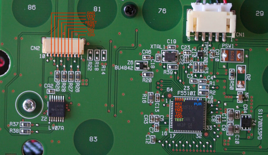
Correctamundo! All of the JTAG and Spy-Bi-Wire connections to the MSP was available in the connector. I whipped out my GoodFET and crossed my fingers hoping that the code protection would not be enabled (not actually believing the memory would be readable). After fighting a bit with the (very broken) FTDI driver in OS X Yosemite I saw some life from the keyboard and the GoodFET, no code protection!? Managed to read out the complete BSL and main flash firmware with the GoodFET without any problems.
So… What to do now? Maybe find out some more about the hardware before diving into the firmware?
Hardware
Some quick Google searches about the chips on the bottom of the circuit board gave an idea about how things was connected. Here are the most interesting ones:
| Symbol | Chip | Function |
|---|---|---|
| Z1 | SN74LV07A | Hex buffer |
| Z2 | SN74LV07A | Hex buffer |
| Z3 | MSP430F5510 | Microcontroller |
| Z5 | SN74LV4051A | Analog (de)multiplexer |
| Z7 | SN74LV07A | Analog (de)multiplexer |
| Z8 | TP1684 | Capacitive switch sense |
| Z9 | AD5258BRMZ50 | 50k digital potentiometer |
By looking at some existing information about Topre keyboards it was easy to sketch out how the switch matrix probably looked.
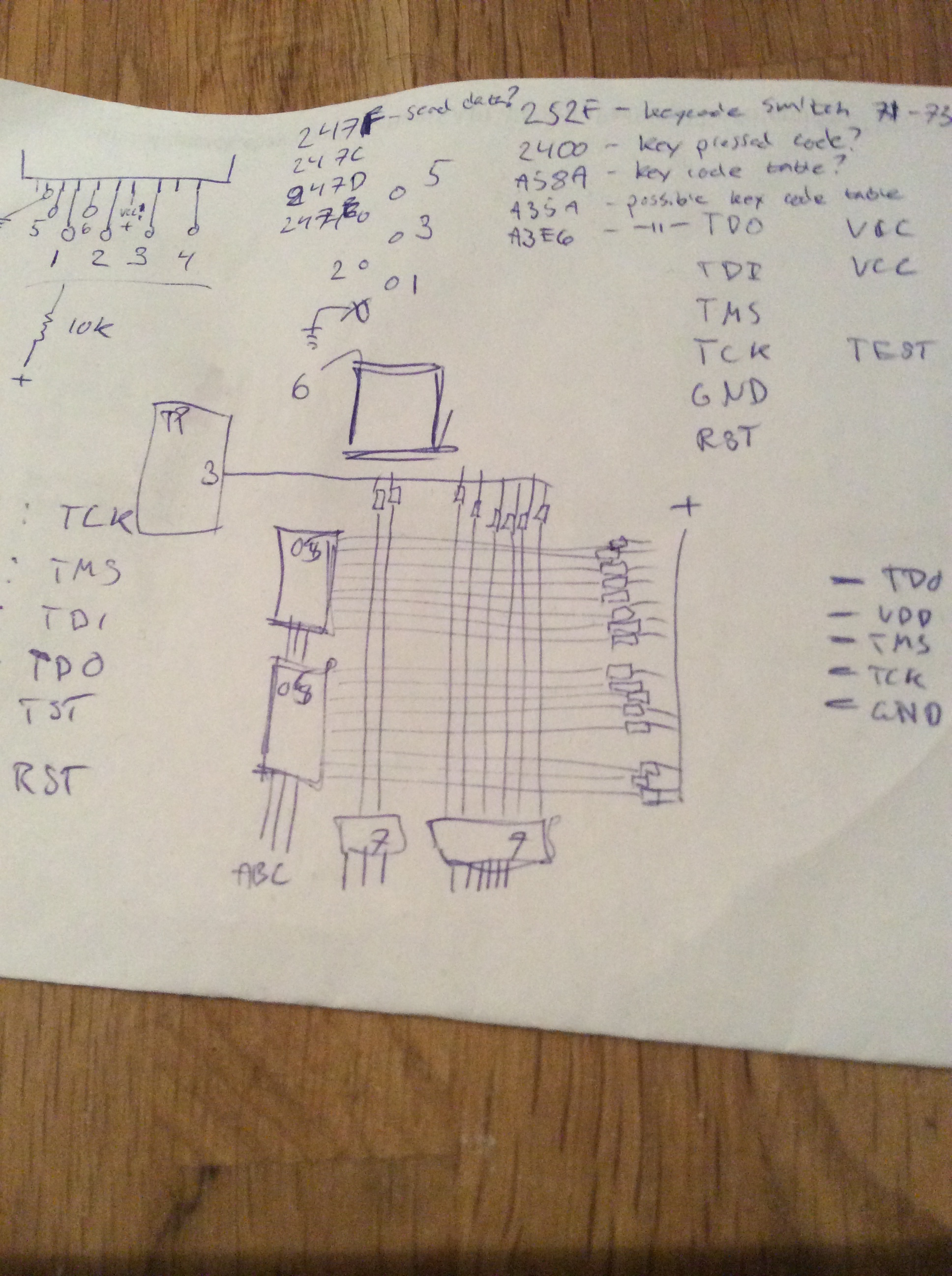
The hardware is a little bit different from the HHKB, instead of using a BCD decoder to select row the Novatouch uses a hex buffer. This consumes some more IOs on the MSP but the function is the same.
By controlling the row and column with the hex buffers and analog multiplexers the controller chooses which switch should be connected to the proprietary Topre capacitive switch sense chip. An interesting part is the digital potentiometer that is connected to the cap sense, seems like it is connected between pins 3 and 6 on the cap sense chip, unfortunately I was not able to find any data-sheet for the cap sense so I’m not sure about it’s function. Was hoping it would be connected to the I2C interface of the MSP so it would be easy to mess around with but it seems to be directly routed to an unpopulated header.
Programming the Digital Potentiometer
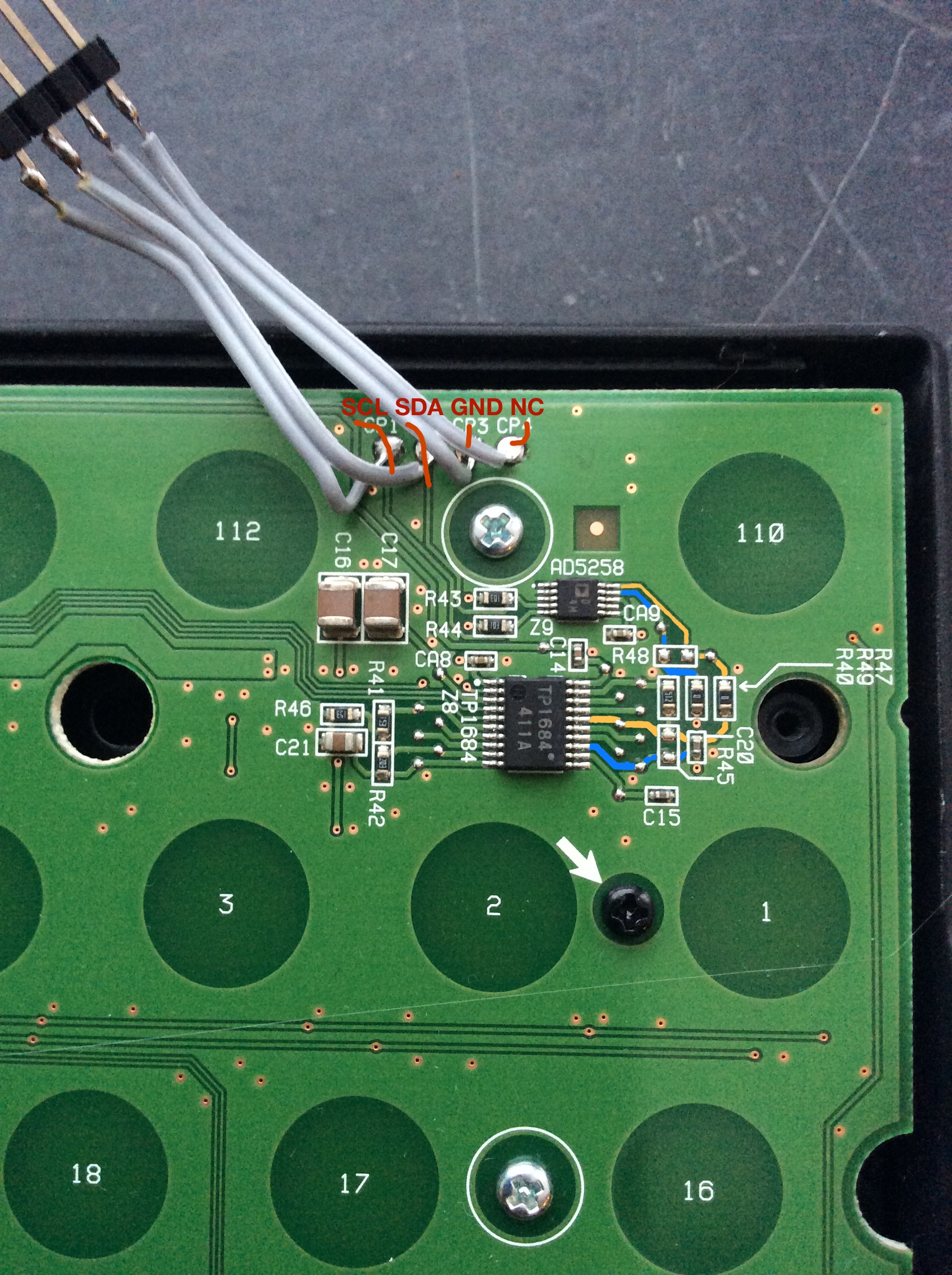
Interested in finding out more about what the digital potentiometer was used for I connected a BusPirate to the I2C bus of the AD5258.
I2C>[ 0x30 0 [ 0x31 r ]
I2C START BIT
WRITE: 0x30 ACK
WRITE: 0x00 ACK
I2C START BIT
WRITE: 0x31 ACK
READ: 0x15 NACK
I2C STOP BIT
Reading RDAC register
Reading out the default value it seemed like the it was programmed to around according to equation from data-sheet (ignoring the fact of device specific calibration which differs up to ..).
By changing the resistance the activation point of the keys changed. A higher resistance made the activation point get lower (the key needs to be pressed down deeper). Lowering the resistance should then make the activation point higher but I'm not sure I noticed any change in my highly scientific testing (holding down a key exactly above the original activation point then reprogramming the resistance and seeing if the keyboard starts sending any keypress).
I2C>[ 0x30 0 0x34 ]
I2C START BIT
WRITE: 0x30 ACK
WRITE: 0x00 ACK
WRITE: 0x34 ACK
I2C STOP BIT
Writing RDAC register (not persistent)
When approaching the upper limit for the resistance some keys stopped registering presses, some of them continued to work if really bottomed out hard. Was a bit surprised that the keys behaved so differently across the board, could not really find any connection between the placement of keys and which keys stopped working. Makes one wonder how the original activation point of the keys between keys differ.
Wrap-up

In this first part of Novatouch teardown I made some analysing of the hardware and how the key matrix looks. In the next part I will do some analysis of the software and see how it can be modified to work more like I want.
comments powered by Disqus