
As written in my first post on this subject I was not really happy with the default mapping of the keys in the Novatouch, this is a writeup of the steps I went through to patch the firmware in the keyboard for a different behaviour. The changes include patching the default key mapping and also adding a hook for entering the TI BSL when a specific key combination is pressed.
Dumping the original firmware
Originally I used a GoodFET for flashing but since then I switched to a Launchpad instead. This made it possible to use the mspdebug tool for remote debugging and flashing. The programming header pinout for JTAG / SWD can be found in the last post.
To be able to open the firmware file in IDA I used objdump from msp-gcc toolchain to create an ELF file from the raw binary dump. Should be possible to import raw binaries into IDA but I did not manage to get it to work in a timely manner. With the ELF I don’t need to go through setting up entry address and memory details every time I re-import the binary. Also, having the object files also makes it simple to link against new code we want to inject.
I have published some tools in my novatools repository with a Makefile that performs all the steps from reading out the firmware to creating the ELF file.
Basically what the Makefile does is:
- Read out the full contents of the main flash with mspdebug (0x8000 - 0xffff)
- Convert resulting ihex to raw binary
- Create separate binary files with the
.textand.vectorssection contents - Do some pathing of the text section
- Compile code to inject into the final ELF
- Create object file from the section binaries
- Create MSP430X ELF file from the object files
The resulting ELF contains the correct entry address and processor model so things get a lot easier when using msp-gcc tools and IDA. Also it’s faster to flash the ELF because half of the contents of the raw binary is just 0xFF.
Firmware analysis
After spending some time in IDA identifying possible functions I got an overall picture of the program flow. Starting out with finding all the IO port manipulation instructions and going from there made things a lot easier (using the IO pin definitions I found out from the hardware analysis).
I also used the source code of the Texas Instruments MSP430 USB developers package as a reference to identify the USB functions of the firmware. My hopes that CoolerMaster was using the reference implementation from TI for USB was confirmed by checking for strings in the raw binary.
$ strings main.elf | grep -i devel
USB_DEVELOPERS_PACKAGE_3_20_00
It seems like the reference implementation is used mostly “as-is” with
some minor modifications. Some changes seem to be back-ported from a
later version of the reference implementation because there are some
functions that look to be more from the 4_00_00 version than
3_20_00.
The firmware uses mostly global variables and barely any local variables, not even via function arguments. This made it easier to figure out each function whenever the purpose of a global variable was identified.
The next chapters describes the overall flow of the program. The flow charts exist just to give an high level understanding of the logic, each chapter describes a single function. All names for variables and functions are made up by me because all I have is the binary with addresses. It’s very possible I have gotten things wrong.
The sleep calls are called sleep_us() but I have no idea whether
it’s actually microseconds. The function loops over a nop (3
instructions per iteration) the number of times specified in argument
so might as well be nanoseconds, depends on what frequency the MSP is
clocked in. Just something I guessed when naming the functions and
never bothered to look up.
Main loop

The main loop does pretty much what’s expected, things like initialising variables and then start to call init functions for different subsystems, including USB.
A loop is then entered where it’s first checked if USB is suspended or not. When USB is in suspend mode the key matrix is still polled to see if any key is pressed. If a key is pressed an USB wakeup is sent to computer.
When USB is active the key sample function is continuously called.
Key sample function

The key sample function reads a single key from the matrix and then handles sending of pending USB reports. A number of USB endpoints are used but I won’t go into details about that. What’s interesting is that the USB key report used only has place for 6 keys (not including modifiers as they are kept as bits in the beginning of the report).
One of the “special features” of the Novatouch is the ability to press
fn + F1-F4 for setting the repeat rate of the keyboard, called rapid
fire. Totally useless function for me but I guess it’s something
gamers find useful. The actual repeating is done at the end of this
function, where the current repeat rate is compared with a timer to
see of the currently pressed key should be sent again.
The mux_and_read function is were all the magic happens.
Key mux and read function

In this function the key mux circuits are controlled by setting the correct row and column for the key that is to be read. A counter keeps track of which key is currently read.
The key index counter is converted into column and row by the bit
pattern xCCCCRRR (R = Row, C = Col). The first C controls which
mux chip should be selected (right or left part of matrix), the two
following CC bits controls the column of the selected chip. The RR
bits selects the row. The counter is cleared when 0x80 is reached.
The current state of each key is kept in a bit packed array with 2 bits for each key. In this array 0 means key is not pressed, 1 means it has just been pressed / is in debounce state and 2 means key is fully pressed.
There seems to be some special handling of the key when it’s in
debounce state, before the key state is read from cap sense controller
the TP_prev IO is set and an extra sleep is performed.
After it has been determined if the key is fully pressed or not (key
state == 2 or 0, debounce logic not shown in figure) the
handle_key_* function is called to handle up / down press. Since the
key down function is very similar to the key up function I have not
done any description of that one, basically just the inverse of the
key up function.
Key down function

When a key is pressed some logic is done to determine what to do for
the key. First thing that is done is that the key index is translated
to a keycode with the help of table_1.
The keycode is used as index into another table (table_2) which
contains which type of key the code corresponds to. The different
types of keys can be seen in the figure above (normal, mod, led). Keys
being of type 0 is passed through and directly put on the USB report
queue to be sent to host.
The handling of rapid fire key combinations can also be found in this
function. Whenever the fn key is pressed a flag is set. If the flag
is set and the current key is F1-F4 a variable is set that is used
to send keys repeatedly at a specific interval when pressed.
The actual sending of the keys is done at the end of the key sample function where a timer is checked to see if enough time has passed for the key to be sent again.
Patching
Now that we have an overview of the program flow we can do some
changes to accomplish our goal; remap caps to ctrl. As can be
seen in the overview in the previous chapter the first thing that
happens when a key is pressed is that it’s looked up in table_1 to
determine it’s keycode. Consequently we should be able to overwrite
the keycode for caps in the table with the code for ctrl instead.
To determine which key index corresponds to which key we could either measure the electical connection between the mux circuits and each key on the PCB or use a debugger to break at each key press to check the global key index variable. To measure the connections between mux and key on PCB it would be necessary to fully disassemble the keyboard and remove the dome sheet, which I was not too keen on. So I went with the debugger route.
Using mspdebug to break on entry to the key pressed function I got the mapping between key index and keycode in the table below.
The row is the lowest 3 bits of key id and the column is the 4 bits above that.
(xCCCCRRR). I.e. tab = 5 + (2«3) = 21.
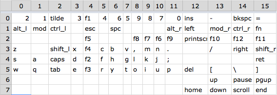
Having this information it was easy to just replace the code for
caps (at index 20) with the code for ctrl (found at index 17) and
manually patch the binary.
After verifying that the new firmware worked I wrote a Python utility for doing the patching automatically, this utility can be found in the novatools repository.
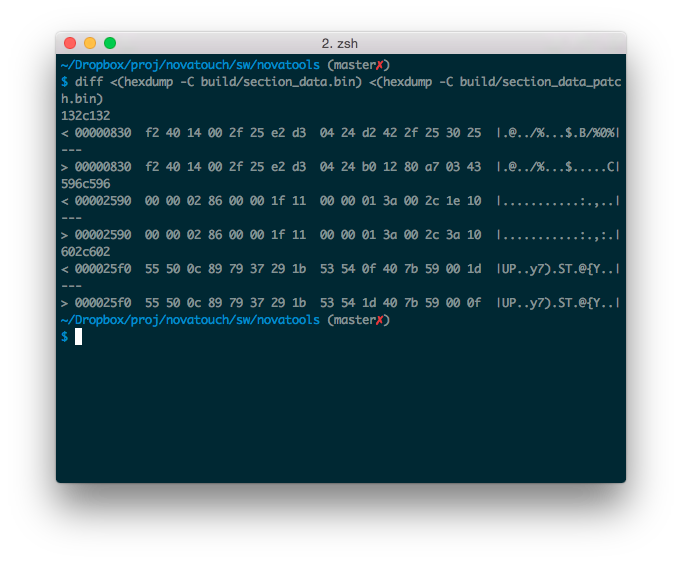
Comparing the original and patched binaries we can see some differences.
First hunk at 0x830 is our call into our own BSL entry check
function (see next chapter). Second hunk at 0x2590 is in table_1
where caps keycode is overwritten with the one for ctrl.
Last hunk switches the backspace and \ keys to get a layout closer
to HHKBr keyboard.
Other than changing around keys we can also change the USB identifier strings and other fun stuff, see patch utility for the addresses of these.
BSL entry hook
To be able to do different key mappings in the future and upgrade the firmware without opening up they keyboard I added a hook for entering the BSL (Bootstrap Loader) by pressing a key combination. The BSL is pre-programmed on all MSP430 processors and can load new firmware via USB. Reading out the BSL memory area with GoodFET showed that the original BSL was still in place.
To enter BSL via code one should just call address 0x1000
according to the documentation from TI. I did a lot of investigation
in the firmware to see if there was any way of entering the BSL without
changing the original firmware. Unfortunately I could not find any way
to do so.
Instead I had to inject some code into the firmware to call the
BSL. The hook is called at the end of the fn + Fx key checking where
I replaced a mov instruction with a call to my own function.
At the end of rapid fire checking in key pressed function we originally had:
...
    8836:	e2 d3 04 24 	bis.b	#2,	&0x2404	;r3 as==10
    883a:	d2 42 2f 25 	mov.b	&0x252f,&0x2530
    883e:	30 25
    8840:	d2 42 2f 25 	mov.b	&0x252f,&0x2531
    8844:	31 25
...
We replace this with a call to our own function which we place at the
end of the .text section at address 0xa780:
...
    8836:	e2 d3 04 24 	bis.b	#2,	&0x2404	;r3 as==10
    883a:	b0 12 80 a7 	calla	#0xa780
    883e:	03 43           nop
    8840:	d2 42 2f 25 	mov.b	&0x252f,&0x2531
    8844:	31 25
...
The opcode for the call instruction was calculated with the help of
the opcode documentation for the 430X instruction set. Because the
call is two bytes shorter than the mov instruction we put a nop
right after our jump.
#include <intrinsics.h>
#include <msp430f5510.h>

// Declare pointers to variables we access in Novatouch fw
unsigned char* const repeat_flags = (unsigned char*)0x2404;
unsigned char* const repeat_rate = (unsigned char*)0x252f;
unsigned char* const num_for_7x_c1 = (unsigned char*)0x2530;

void check_bsl_enter() {
    // We just replaced this copy to get here, perform it here instead
    // (although it seems to be redundant because it's never actually
    // read)
    *num_for_7x_c1 = *repeat_rate;

    // Enter BSL if fn + f1 + f4 is pressed
    if (*repeat_flags & 0x9) {
        __dint();
        // Maybe need to slow down clock to 8 MHz also, not sure what
        // is configured by Novatouch fw
        USBKEYPID = 0x9628;
        USBCNF &= ~PUR_EN;
        USBPWRCTL &= ~VBOFFIE;
        USBKEYPID = 0x9600;
        ((void (*)())0x1000)();
    }
}
This code snipped is compiled into an object file with msp430-gcc
and linked together with our original firmware. For details look at
the Makefile in novatools.
Unfortunately this did not help me a whole lot because OS X promptly refused to enumerate the HID device the BSL exposes and therefore I could not even route the USB device to a virtual machine. Will need to find a PC to do the upgrade the next time I want to change the firmware without opening up the case.
Further work
This concludes my current adventures in Novatouch land. In retrospective when looking over this post it feels like I could have left out half of it and just write about the interesting parts (patching and injecting code) instead of trying to explain the whole program flow. Well, since this is an experiment in trying to get better at writing at least I have something to better for the next post.
Therea are some things I would like to do further work on that I have not yet had time for:
- Hook up oscilloscope to cap sense controller and try to understand how it works (need to find an oscilloscope first)
- Write HHKB fn layer to have easier access to arrows and F keys
- Or just port tmk_keyboard or some other open source firmware
- Exploit USB stack to be able to enter BSL without ever opening the keyboard